The board is a derivative of the Boarduino, which was developed by Limor Fried (a.k.a. Lady Ada).
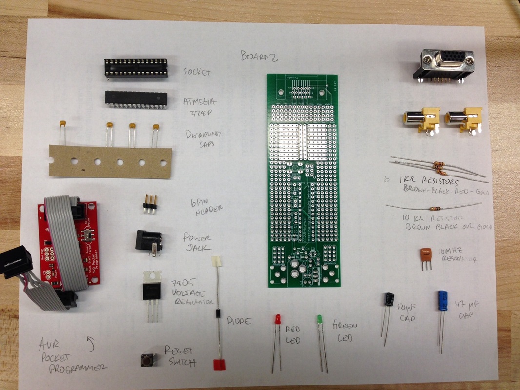
First, make sure that you have all of the parts:
Follow her tutorial here:
http://learn.adafruit.com/boarduino-kits
Alternatively, MAKE has a similar tutorial here:
http://makezine.com/2008/05/30/build-make-a-boarduino/
Note a few minor differences:
http://learn.adafruit.com/boarduino-kits
Alternatively, MAKE has a similar tutorial here:
http://makezine.com/2008/05/30/build-make-a-boarduino/
Note a few minor differences:
- We are using a six pin programming header
- Make sure to include the reset button...not everyone includes this
- We have omitted the "legs" of the DIP that are usually on the boarduino
- Use your power brick from your larger kit to power the board. Even though the programmer can be used to power the system, I have always found the connection to be a bit flaky.
We have added a few extra bells and whistles. There is a VGA connector and two RCA jacks on the board
Also include these and solder them in.
Also include these and solder them in.
Final extra connections:
Add the following connectors:
-Short together (using a length of wire) VGA pins 5, 6, 7, 8, and 10
-Connect VGA 10 to ground (pin 22 of the ATMEGA 328P)
-Connect a 1K resistor between VGA1 and pin 3 of the ATMEGA 328P (labelled tx on the board)
-Short together VGA1, 2, and 3
-Connect pin 5 on the ATMEGA 328P (labelled d3) to VGA 13
-Connect pin 16 on the ATMEGA 328P (labelled 10) to VGA 14
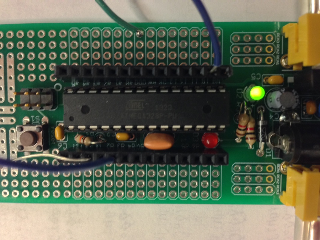
I've added some headers to my board for prototyping...you don't need them (you can solder right into the board) but are welcome to add them if you like.
Add the following connectors:
-Short together (using a length of wire) VGA pins 5, 6, 7, 8, and 10
-Connect VGA 10 to ground (pin 22 of the ATMEGA 328P)
-Connect a 1K resistor between VGA1 and pin 3 of the ATMEGA 328P (labelled tx on the board)
-Short together VGA1, 2, and 3
-Connect pin 5 on the ATMEGA 328P (labelled d3) to VGA 13
-Connect pin 16 on the ATMEGA 328P (labelled 10) to VGA 14
I've added some headers to my board for prototyping...you don't need them (you can solder right into the board) but are welcome to add them if you like.
|
Arduino pin name
Ground Tx/1 D03 D10 |
ATMEGA 328p pin number
22 3 5 16 |
Board label
gnd tx D3 10 |
What is it?
Ground (0V reference) The video signal HSYNC VSYNC |
Target connection
VGA 5, 6, 7, 8, 10 VGA 1,2,3 VGA 13 VGA 14 |
Once you're done, you're ready to move on to the next step, which is programming the board as an Arduino unit!
